Difference between revisions of "Complete Electronics Tutorial"
(→Useful Electronic Devices) |
MachineMan (talk | contribs) (→FILT and SPRK) |
||
| (45 intermediate revisions by 12 users not shown) | |||
| Line 1: | Line 1: | ||
This page is currently a work in progress. | This page is currently a work in progress. | ||
| − | The goal of this page is to be a complete electronics tutorial for new players and seasoned ones who want to learn more about electronics, and to replace the | + | The goal of this page is to be a complete electronics tutorial for new players and seasoned ones who want to learn more about electronics, and to replace the existing electronics tutorial that has not been updated since 2011. |
==Intro to Electronics== | ==Intro to Electronics== | ||
| Line 11: | Line 11: | ||
====How SPRK Works==== | ====How SPRK Works==== | ||
| − | SPRK, found in the electronics menu, is the basis of all electronics in TPT. SPRK is an indestructible solid that cannot be placed, but it can be "drawn" on to metals and conductive elements | + | SPRK, found in the electronics menu, is the basis of all electronics in TPT. SPRK is an indestructible solid that cannot be placed, but it can be "drawn" on to metals and conductive elements. SPRK will transfer itself to any conductive elements within 2 pixels. This allows SPRK to move along conductive elements, which include all metals, WATR and SLTW, MERC, and QRTZ (when under pressure). As seen below, different conductors (METL, GOLD, WATR, and SLTW) conduct at different speeds. |
| − | + | [[File:1-6-Conductivity.gif]] | |
| − | + | =====Technical Details===== | |
| + | When a conductive element is sparked, it is replaced with SPRK and the ctype of the SPRK is set to that element. The life of the SPRK is set to 4 and when it reaches 0, the SPRK will replace itself with its ctype, allowing it to turn back into the original element, but with a life set back to 4. The conductor will not be sparkable again until the life reaches 0 - meaning that 8 frames are required for one complete spark cycle. | ||
====Basic Conductors==== | ====Basic Conductors==== | ||
| Line 39: | Line 40: | ||
====Using INSL==== | ====Using INSL==== | ||
| − | + | Another useful electronic element is INSL, which completely blocks heat and electricity. This can be used to prevent SPRK from jumping over a 1-pixel gap. | |
[[File:1-5-INSL.gif]] | [[File:1-5-INSL.gif]] | ||
| Line 51: | Line 52: | ||
===Using WIFI to Transfer Electricity=== | ===Using WIFI to Transfer Electricity=== | ||
| − | WIFI makes it easy to transfer electricity instantly over long distances instead of using long wires. WIFI takes electricity from | + | WIFI makes it easy to transfer electricity instantly over long distances instead of using long wires. WIFI takes electricity from all conductors except NSCN, and will pass electricity to any NSCN, PSCN, or INWR. After placing a pixel of WIFI (it must be used in single pixels), you have to set the channel. WIFI has 100 temperature-dependent channels located every 100 degrees, which can be set manually using the PROP tool, but the recommended way is to use jacob1's Set WIFI script found in the [https://powdertoy.co.uk/Discussions/Thread/View.html?Thread=19400 Lua Script Manager]. This useful tool simply asks you to input the channel number and sets it for you. As seen in the picture, WIFI's color is dependent on its channel. |
[[File:1-9-WIFI.gif]] | [[File:1-9-WIFI.gif]] | ||
| Line 57: | Line 58: | ||
===Using INST=== | ===Using INST=== | ||
| − | INST is another way to transfer electricity instantly over long distances, but in the form of a wire. Unlike other conductive elements, INST can only take electricity from PSCN and can only conduct to NSCN. It can not conduct to itself over 1-pixel gaps, and it can cross over itself freely, making it possibly one of the most useful electronic elements. | + | INST is another way to transfer electricity instantly over long distances, but in the form of a wire. Unlike other conductive elements, INST can only take electricity from PSCN and can only conduct to NSCN and GOLD. It can not conduct to itself over 1-pixel gaps, and it can cross over itself freely, making it possibly one of the most useful electronic elements. |
[[File:1-7-INST.gif]] | [[File:1-7-INST.gif]] | ||
| Line 65: | Line 66: | ||
===ARAY Basics=== | ===ARAY Basics=== | ||
| − | ARAY is an element that allows another way of transferring electricity over a long distance, and it is also the fastest conductor in the game. Unlike other electronic elements, it must be triggered by an adjacent conductor, which must be METL, PSCN (which will be covered later), or INST. When triggered, it emits a line of BRAY (a hidden solid element) that fades away after 30 frames. If this BRAY hits a conductor, it will spark it. | + | ARAY is an element that allows another way of transferring electricity over a long distance, and it is also the fastest conductor in the game, which helps with making electronic devices more compact and faster. Unlike other electronic elements, it must be triggered by an adjacent conductor, which must be METL, PSCN (which will be covered later), or INST. When triggered, it emits a line of BRAY (a hidden solid element) that fades away after 30 frames. If this BRAY hits a conductor, it will spark it. |
[[File:2-1-ARAY.gif]] | [[File:2-1-ARAY.gif]] | ||
| − | If 2 of these BRAY rays collide, it will create a "point" of BRAY that lasts for 1020 frames. | + | If 2 of these BRAY rays collide, it will create a "point" of BRAY that lasts for 1020 frames. |
| − | [[File:2-2-Point.gif]] | + | [[File:2-2-Point.gif]] |
| − | + | If two BRAYs pass next to each other, even if they are touching, nothing will happen. This makes BRAY useful as a way to make compact connections by transmitting many BRAY beams next to each other. | |
===Useful ARAY Tricks=== | ===Useful ARAY Tricks=== | ||
| Line 85: | Line 86: | ||
====Using ARAY with FILT==== | ====Using ARAY with FILT==== | ||
| − | FILT can be used to remove the 30-frame delay when firing ARAY, making it the fastest way to conduct electricity. Simply draw FILT where the BRAY beam will be, and use the ARAY. BRAY will disappear instantly inside FILT, and beams can intersect without creating points. BRAY that passes through FILT will | + | FILT can be used to remove the 30-frame delay when firing ARAY, making it the fastest way to conduct electricity. Simply draw FILT where the BRAY beam will be, and use the ARAY. BRAY will disappear instantly inside FILT, and beams can intersect without creating points. BRAY that passes through FILT will take on the wavelength of the FILT. |
[[File:2-3-FILT.gif]] | [[File:2-3-FILT.gif]] | ||
| Line 91: | Line 92: | ||
====Using ARAY with INST==== | ====Using ARAY with INST==== | ||
| − | One more useful feature of ARAY is that if it is triggered with INST, the BRAY beam will pass through multiple conductors. | + | One more useful feature of ARAY is that if it is triggered with INST, the BRAY beam will pass through multiple conductors. The INST-BRAY beam can be stopped with INSL. |
[[File:2-5-INST_ARAY.gif]] | [[File:2-5-INST_ARAY.gif]] | ||
| Line 98: | Line 99: | ||
===PTCT/NTCT Basics=== | ===PTCT/NTCT Basics=== | ||
| + | |||
| + | PTCT and NTCT are elements found in the electronics menu that conduct electricity based on how hot they are. PTCT only conducts when cold (<100 degrees) and NTCT only conducts when hot (>100 degrees). The easiest way to heat them is to spark a pixel of METL placed 1 pixel away, as PTCT and NTCT heat up to 200 degrees when there's sparked METL nearby. | ||
| + | |||
| + | The image below shows PTCT (bottom) and NTCT (top) in action. | ||
| + | |||
| + | [[File:3-1-PTCT NTCT.gif]] | ||
===Logic Gates=== | ===Logic Gates=== | ||
| + | |||
| + | If you are new to TPT and electronic engineering, you might be wondering what logic gates are. Logic gates are electronic devices that create an output based on inputs they receive. They work the same way in real-life electronic circuits and in TPT. Every basic logic gate has 2 inputs (with the exception of the NOT gate) and 1 output. Both the inputs and the output can be one of two states: ON and OFF, HIGH and LOW, or 1 and 0. In TPT, ON/HIGH/1 means that the output is sparked and OFF/LOW/0 means that it is not sparked. This tutorial will use HIGH and LOW. | ||
| + | |||
| + | While PTCT and NTCT can be used to make logic gates, they have mostly been replaced by much faster logic gates made using advanced ARAY techniques, which you will learn about later. However, it is still a good idea to learn how PTCT/NTCT logic works, because you might see it when looking at older electronics saves. | ||
| + | |||
| + | ====OR Gates==== | ||
| + | |||
| + | An OR gate is a logic gate that will output HIGH if either of its inputs or both of its inputs are HIGH and the easiest to make in TPT as it consists of 2 diodes with the output connected together. | ||
| + | |||
| + | [[File:3-3-Or.gif]] | ||
| + | |||
| + | ====AND Gates==== | ||
| + | |||
| + | An AND gate will only output HIGH when both of its inputs are HIGH. It is the easiest-to-understand logic gate using the old technology. | ||
| + | |||
| + | [[File:3-2-And.gif]] | ||
| + | |||
| + | ====XOR Gates==== | ||
| + | |||
| + | A XOR gate (eXclusive OR) will only output HIGH if one of its inputs is HIGH (not both). It is one of the more complicated gates to create at a small size in TPT, but luckily someone has already done that for you. | ||
| + | |||
| + | [[File:3-4-Xor.gif]] | ||
| + | |||
| + | ====NOT Gates==== | ||
| + | |||
| + | Unlike the other logic gates here, a NOT gate only has one input and will only output HIGH if the input is low. This is easy to do with PTCT, which will not conduct when heated. | ||
| + | |||
| + | [[File:3-5-Not.gif]] | ||
| + | |||
| + | ====NOR Gates==== | ||
| + | |||
| + | A NOR gate (Not OR) can be thought of as an OR gate with a NOT gate connected to the output. It will only output HIGH if none of its inputs are HIGH. | ||
| + | |||
| + | [[File:3-6-Nor.gif]] | ||
| + | |||
| + | ====NAND Gates==== | ||
| + | |||
| + | A NAND gate (Not AND) can be thought of as an AND gate with a NOT gate connected to the output. It will only output HIGH if none or 1 of its inputs is HIGH. | ||
| + | |||
| + | [[File:3-7-Nand.gif]] | ||
| + | |||
| + | ====XNOR Gates==== | ||
| + | |||
| + | A XNOR gate (eXclusive Not OR) can be thought of as a XOR gate with a NOT gate connected to the output. It will only output HIGH if none or both of its inputs are HIGH. | ||
| + | |||
| + | [[File:3-8-Xnor.gif]] | ||
==Useful Electronic Devices== | ==Useful Electronic Devices== | ||
| + | This section will show some useful basic electronic components that can be created with the elements shown so far. | ||
| + | |||
| + | ===SWCH Memory=== | ||
| + | |||
| + | Because SWCH maintains its state when turned on or off, it can be used to make the simplest form of memory in TPT: | ||
| + | |||
| + | [[File:5-1-SWCH RAM 1.gif]] | ||
| + | |||
| + | ARAY is used to spark PSCN within the conduction range of the SWCH, which turns it on, writing to the memory. INST is used to trigger ARAY which activates more ARAY directed through the SWCH. The BRAY will only pass through pixels of SWCH which are turned on by the PSCN, which effectively allows the memory to be read. Another INST-triggered ARAY sparks a pixel of NSCN next to each pixel of SWCH, which clears the memory. | ||
| + | |||
| + | SWCH memory can be made more compact, as shown in this example: | ||
| + | |||
| + | [[File:5-2-SWCH RAM 2.gif]] | ||
| + | |||
| + | This is done simply by moving everything closer together, using INSL as needed to prevent unwanted SPRK transfer. SWCH memory can be made even smaller by layering, which is beyond the scope of this tutorial. Larger arrays of SWCH memory are also possible, but are now considered obsolete because of CRAY memory, which is shown later. | ||
| + | |||
| + | ===Shift Registers=== | ||
| + | |||
| + | By modifying the concept of SWCH memory, a shift register can be made. A shift register takes input data, either as serial (a series of pulses on one wire) or parallel (pulses on several wires), and can shift it in one direction, giving either a parallel or serial output. A serial-in parallel-out shift register is shown below. | ||
| + | |||
| + | [[File:5-3-SIPO Shift Register.gif]] | ||
| + | |||
| + | Parallel-in serial-out shift registers can also be created: | ||
| + | |||
| + | [[File:5-4-PISO Shift Register.gif]] | ||
| + | |||
| + | A simple serial data link can be made using a parallel-in serial-out shift register to send data and a serial-in parallel-out shift register to receive data. This is the same principle by which real-life serial data protocols like USB and RS-232 work in hardware. However, in TPT, there is a much faster and simpler way of sending data serially using BRAY and FILT wavelengths which is shown later. | ||
| + | |||
| + | ====Decimal Counters==== | ||
| − | + | A simple decimal counter can be made by connecting the last output of a serial-in parallel-out shift register to its input. The counter will increment by one every time the shift input is sparked: | |
| − | + | [[File:5-5-Decimal Counter.gif]] | |
| − | + | By removing any unnecessary parts, it can be made even smaller: | |
| − | + | [[File:5-6-Decimal Counter 2.gif]] | |
| − | ==Using | + | ====Shift Register Latches==== |
| + | |||
| + | In order to read the output of a serial-in parallel-out shift register without shifting it, you can add SWCH memory to the output and connect the ARAY that reads the memory to the INST that shifts the register. | ||
| + | |||
| + | [[File:5-7-Shift Register Latch.gif]] | ||
| + | |||
| + | ===Decimal to Binary Converters=== | ||
| + | |||
| + | Another property of ARAY can be used to make a simple decimal to binary converter: | ||
| + | |||
| + | [[File:5-8-Decimal To Binary.gif]] | ||
| + | |||
| + | The horizontal ARAYs spark the NSCN, which sparks the INWR, which sparks the ARAYs that point to the output. This works because BRAY passes harmlessly through any INWR and ARAY in its path. The example only outputs a 3-bit binary number, but can easily be expanded. | ||
| + | |||
| + | ===Binary to Decimal Converters=== | ||
| + | |||
| + | Binary to decimal converters can be made by toggling SWCH in specific patterns for each bit and firing ARAY through it: | ||
| + | |||
| + | [[File:5-9-Binary To Decimal.gif]] | ||
| + | |||
| + | Binary to decimal converters using advanced ARAY techniques (shown later) are smaller but more complicated to make. | ||
| + | |||
| + | ==Using Other Electronic Elements== | ||
===Using DLAY=== | ===Using DLAY=== | ||
| + | |||
| + | DLAY is an electronic element found in the powered elements menu. It only conducts from PSCN to NSCN and creates a delay for an amount of frames determined by its temperature. The default temperature is 4 degrees, which will create a 4-frame delay. | ||
| + | |||
| + | [[File:4-1-DLAY.gif]] | ||
===Using FRAY=== | ===Using FRAY=== | ||
| + | |||
| + | FRAY is an electronic element that pushes or pulls particles when sparked based on its temperature. A positive temperature will push particles and a negative temperature will pull on them. With a high enough temperature, a single particle can be accelerated enough to break GLAS. | ||
| + | |||
| + | [[File:4-2-FRAY.gif]] | ||
===Using STOR=== | ===Using STOR=== | ||
| − | + | STOR is an electronic element that stores a single particle and releases it when powered with PSCN. It can be used to precisely dispense single particles instead of using PPIP. It can also directly pass to an adjacent PIPE or PPIP without any PSCN input. | |
| + | |||
| + | [[File:4-3-STOR.gif]] | ||
===Using Sensors=== | ===Using Sensors=== | ||
| − | ===Using | + | There are 3 sensors in TPT which are all found in the sensors menu. They are DTEC, which sparks any nearby conductors if it detects a particle of its ctype in its detection range (this is set by tmp2, see the DTEC page for details), TSNS, which sparks any nearby conductors if it is touching a particle with a temperature higher than its own, and PSNS, which sparks any nearby conductors when the pressure is higher than its temperature. |
| + | |||
| + | ===Using Powered Elements=== | ||
| + | |||
| + | ====LCRY==== | ||
| + | |||
| + | LCRY is a powered element that is activated by PSCN and deactivated by NSCN. By default, it will change color to a lighter gray when turned on, but if it has a decoration color, it will be black when off and it will change to its decoration color when on. | ||
====PUMP and GPMP==== | ====PUMP and GPMP==== | ||
| Line 131: | Line 251: | ||
====HSWC==== | ====HSWC==== | ||
| − | HSWC is a powered element that is | + | HSWC is a powered element that is activated by PSCN and deactivated by NSCN. When turned off it does not conduct heat, but when turned on it conducts heat quickly. |
| − | ====PCLN/PBCN/PVOD==== | + | ====PCLN/PBCN/PVOD/PPIP==== |
| − | These are all powered elements activated by PSCN and deactivated by NSCN that act as CLNE, BCLN, and | + | These are all powered elements activated by PSCN and deactivated by NSCN that act as CLNE, BCLN, VOID, and PIPE when turned on. |
| − | ==Using CRAY and PSTN== | + | ==Using CRAY, DRAY, and PSTN== |
===Using CRAY=== | ===Using CRAY=== | ||
| + | |||
| + | CRAY is similar to ARAY except that it emits a beam of any other particles. The particle type that it emits can be set using its ctype or by drawing over it with an element. The temperature of the emitted particles is determined by the temperature of the CRAY. | ||
| + | |||
| + | CRAY can emit particle beams in 8 directions: | ||
| + | |||
| + | [[File:6-1-CRAY 1.gif]] | ||
| + | |||
| + | The tmp property of CRAY changes the length of the particle beam... | ||
| + | |||
| + | [[File:6-2-CRAY Tmp.gif]] | ||
| + | |||
| + | and the tmp2 property changes the number of pixels skipped before the beam starts: | ||
| + | |||
| + | [[File:6-3-CRAY Tmp2.gif]] | ||
| + | |||
| + | By placing FILT in front of CRAY, the decoration color of the emitted particles can be set: | ||
| + | |||
| + | [[File:6-4-CRAY FILT.gif]] | ||
| + | |||
| + | ====CRAY Modes==== | ||
| + | |||
| + | CRAY can be used in different modes by sparking it through different elements: | ||
| + | |||
| + | [[File:6-5-CRAY Types.gif]] | ||
| + | |||
| + | When sparked through METL, the CRAY beam will stop at the first particle other than FILT in its path. When sparked through PSCN, the CRAY beam will, for every pixel in its path, if the pixel is occupied by a particle it will be erased, and if the pixel is not occupied by a particle one will be created. When sparked through INWR, as many particles as the CRAY's tmp value will be created, ignoring but not overwriting any particles already in its path. | ||
| + | |||
| + | ===Using DRAY=== | ||
===Using PSTN=== | ===Using PSTN=== | ||
| − | + | PSTN is an electronic element that moves other particles. The most basic way to use PSTN is to place two pixels of PSTN with a pixel of PSCN and NSCN each one pixel away. PSTN extends when the PSCN is sparked and retracts when the NSCN is sparked. | |
| + | |||
| + | [[File:6-6-PSTN.gif]] | ||
| − | + | By default, PSTN is sticky, meaning it will pull particles back when it retracts. This can be changed, as you will see later. | |
| − | ==== | + | [[File:6-7-PSTN Sticky.gif]] |
| + | |||
| + | A common way to use PSTN in electronics is to place a particle of METL or DLAY so the PSCN conducts to it and then to the NSCN so the PSTN automatically retracts. | ||
| + | |||
| + | [[File:6-10-PSTN Autoretract.gif]] | ||
| + | |||
| + | ====Using FRME==== | ||
| + | |||
| + | When PSTN pushes one particle of FRME with others touching it, all of the FRME particles will move at the same time. This allows PSTN to move many particles at once. | ||
| + | |||
| + | [[File:6-11-PSTN FRME.gif]] | ||
| + | |||
| + | FRME can be made non-sticky by changing its tmp value to 1. | ||
| + | |||
| + | [[File:6-12-PSTN FRME Nonsticky.gif]] | ||
| + | |||
| + | ====Using PSTN's Temperature==== | ||
| + | |||
| + | The distance by which PSTN extends each frame can be controlled by either making the PSTN longer and moving the PSCN and NSCN further away from the extending end, or by setting the temperature of the PSTN. PSTN extends by its temperature in degrees above 0C divided by 10 and rounded to the nearest whole number, summed over all PSTN particles from the one receiving the spark to the one at the extending end of the PSTN, all minus one particle. | ||
| + | |||
| + | This save demonstrates how to use PSTN's temperature to make PSTN that can instantly extend the distance specified by a binary input: | ||
| + | {{ save | id=2038496 }} | ||
| + | |||
| + | ====Other PSTN Properties==== | ||
| + | |||
| + | PSTN's ctype determines what particle type it will stop extending at if it hits. | ||
| + | |||
| + | [[File:6-9-PSTN Ctype.gif]] | ||
| + | |||
| + | PSTN's tmp2 can be used in a similar way to limit the maximum extension length. | ||
| + | |||
| + | [[File:6-8-PSTN Tmp2.gif]] | ||
| + | |||
| + | PSTN's tmp can be used to set the maximum number of particles it can move. | ||
==Advanced ARAY Usage== | ==Advanced ARAY Usage== | ||
| − | === | + | ===Erase BRAY=== |
| + | |||
| + | When ARAY is sparked with PSCN, it creates orange BRAY called erase BRAY. Erase BRAY does not spark objects, disappears in 2 frames, unlike normal BRAY which disappears in 30 frames, and erases any other BRAY in its path. | ||
| + | |||
| + | [[File:7-1-Erase BRAY.gif]] | ||
| + | |||
| + | INST-ARAY and PSCN-ARAY can be combined to fire normal BRAY which is then quickly erased, allowing the normal BRAY to spark its target every 4 frames without needing FILT in its path.. | ||
| + | |||
| + | [[File:7-2-Auto-Erase BRAY.gif]] | ||
| + | |||
| + | ARAY life property can be changed to make BRAY disappear faster or last longer allowing for a custom ARAY cooldown. | ||
| + | |||
| + | [[File:7-3-BRAY-life.gif]] | ||
| + | |||
| + | ===Binary Counters=== | ||
| + | |||
| + | ===FILT ROM=== | ||
===Faster Logic Gates=== | ===Faster Logic Gates=== | ||
| − | === | + | ===CRAY RAM=== |
| + | |||
| + | ===ARAY and FILT Wavelengths=== | ||
| + | |||
| + | ====FILT and SPRK==== | ||
| + | Working with parallel SPRK data is simpler but the machines are large and clunky; working with serial FILT data allows for more compact and faster machines, but FILT bits are more complex. What if you could have the best of both world's; now you can. | ||
| + | |||
| + | Here are designs for a parallel SPRK to serial FILT converter and a serial FILT to parallel SPRK converter: | ||
| + | {{save | id=3096036}} | ||
| − | == | + | ====Better FILT ROM==== |
Latest revision as of 06:27, 2 May 2024
This page is currently a work in progress.
The goal of this page is to be a complete electronics tutorial for new players and seasoned ones who want to learn more about electronics, and to replace the existing electronics tutorial that has not been updated since 2011.
Contents
Intro to Electronics
This section is primarily for new players, so if you already know about the basics of electricity, SWCH, WIFI, and INST, you can skip ahead to the next section.
Basics of Electricity in TPT
How SPRK Works
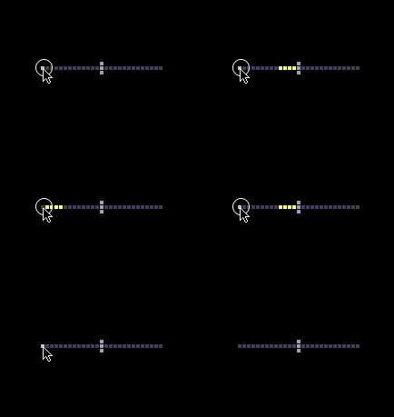
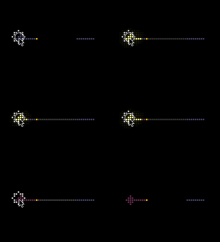
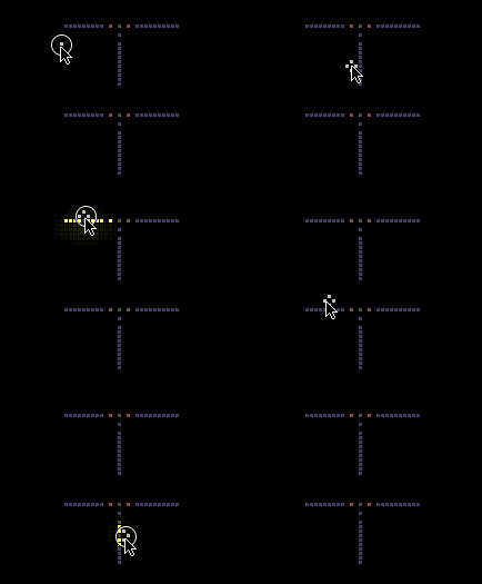
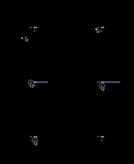
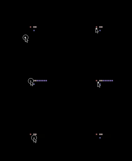
SPRK, found in the electronics menu, is the basis of all electronics in TPT. SPRK is an indestructible solid that cannot be placed, but it can be "drawn" on to metals and conductive elements. SPRK will transfer itself to any conductive elements within 2 pixels. This allows SPRK to move along conductive elements, which include all metals, WATR and SLTW, MERC, and QRTZ (when under pressure). As seen below, different conductors (METL, GOLD, WATR, and SLTW) conduct at different speeds.
Technical Details
When a conductive element is sparked, it is replaced with SPRK and the ctype of the SPRK is set to that element. The life of the SPRK is set to 4 and when it reaches 0, the SPRK will replace itself with its ctype, allowing it to turn back into the original element, but with a life set back to 4. The conductor will not be sparkable again until the life reaches 0 - meaning that 8 frames are required for one complete spark cycle.
Basic Conductors
The most basic conductors are METL, PSCN, and NSCN, which are found in the electronics menu. These are what you will use most of the time to transfer electricity. METL conducts to both PSCN and NSCN, and both PSCN and NSCN conduct to metal, as demonstrated below.
However, things get a bit complicated. While PSCN conducts to both METL and NSCN, NSCN cannot conduct to PSCN.
This behavior can be used to make a diode, which allows electricity to flow only one way.
Using BTRY
BTRY is an element that can be used to constantly spark any conductor. Simply place one pixel of it and it will work.
Using INSL
Another useful electronic element is INSL, which completely blocks heat and electricity. This can be used to prevent SPRK from jumping over a 1-pixel gap.
Using SWCH to Control Electronics
SWCH is an element that is used to control the flow of electricity by turning it on and off. SWCH is turned on and off by PSCN and NSCN, like many other powered elements you will learn about later, and conducts to and from METL.
Using WIFI to Transfer Electricity
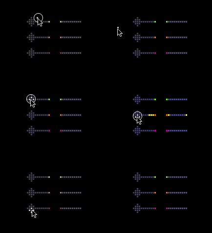
WIFI makes it easy to transfer electricity instantly over long distances instead of using long wires. WIFI takes electricity from all conductors except NSCN, and will pass electricity to any NSCN, PSCN, or INWR. After placing a pixel of WIFI (it must be used in single pixels), you have to set the channel. WIFI has 100 temperature-dependent channels located every 100 degrees, which can be set manually using the PROP tool, but the recommended way is to use jacob1's Set WIFI script found in the Lua Script Manager. This useful tool simply asks you to input the channel number and sets it for you. As seen in the picture, WIFI's color is dependent on its channel.
Using INST
INST is another way to transfer electricity instantly over long distances, but in the form of a wire. Unlike other conductive elements, INST can only take electricity from PSCN and can only conduct to NSCN and GOLD. It can not conduct to itself over 1-pixel gaps, and it can cross over itself freely, making it possibly one of the most useful electronic elements.
Basic ARAY Usage
ARAY Basics
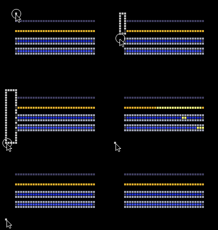
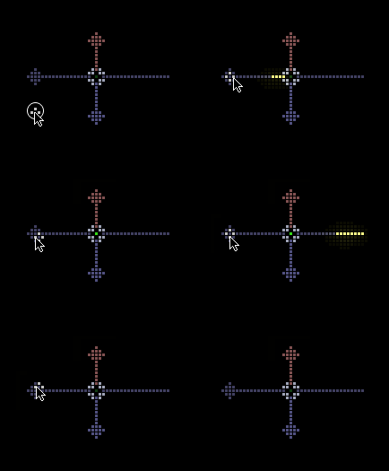
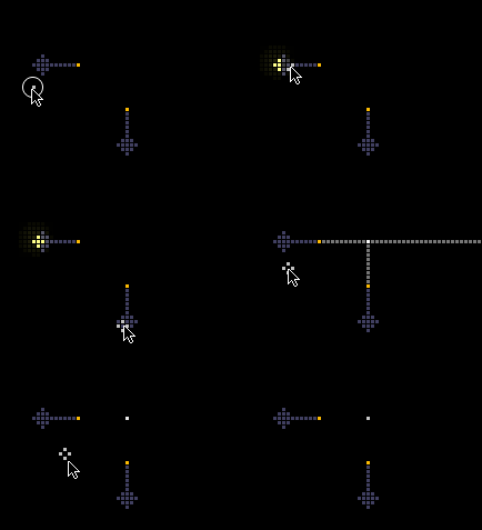
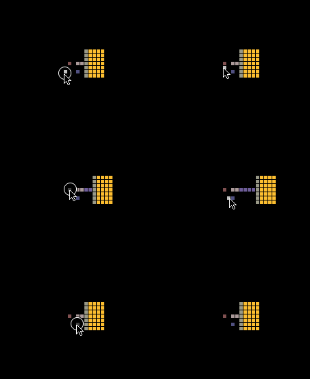
ARAY is an element that allows another way of transferring electricity over a long distance, and it is also the fastest conductor in the game, which helps with making electronic devices more compact and faster. Unlike other electronic elements, it must be triggered by an adjacent conductor, which must be METL, PSCN (which will be covered later), or INST. When triggered, it emits a line of BRAY (a hidden solid element) that fades away after 30 frames. If this BRAY hits a conductor, it will spark it.
If 2 of these BRAY rays collide, it will create a "point" of BRAY that lasts for 1020 frames.
If two BRAYs pass next to each other, even if they are touching, nothing will happen. This makes BRAY useful as a way to make compact connections by transmitting many BRAY beams next to each other.
Useful ARAY Tricks
Using ARAY with SWCH
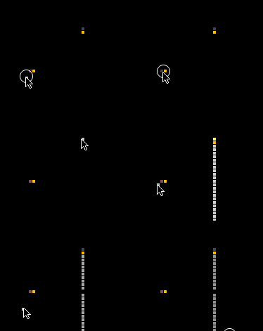
Along with switching electricity on and off, SWCH can also be used to control BRAY. When SWCH is on, BRAY can freely pass through, but when it is off, BRAY is blocked.
Using ARAY with FILT
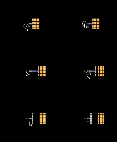
FILT can be used to remove the 30-frame delay when firing ARAY, making it the fastest way to conduct electricity. Simply draw FILT where the BRAY beam will be, and use the ARAY. BRAY will disappear instantly inside FILT, and beams can intersect without creating points. BRAY that passes through FILT will take on the wavelength of the FILT.
Using ARAY with INST
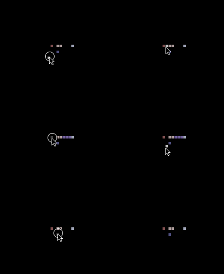
One more useful feature of ARAY is that if it is triggered with INST, the BRAY beam will pass through multiple conductors. The INST-BRAY beam can be stopped with INSL.
Using PTCT and NTCT To Make Logic Gates
PTCT/NTCT Basics
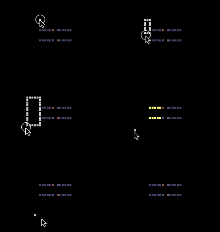
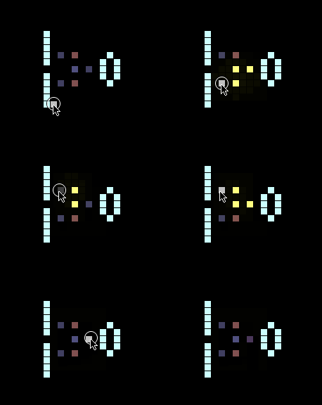
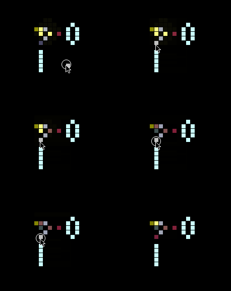
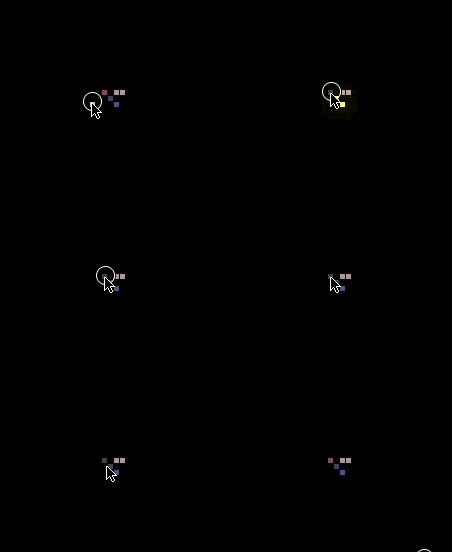
PTCT and NTCT are elements found in the electronics menu that conduct electricity based on how hot they are. PTCT only conducts when cold (<100 degrees) and NTCT only conducts when hot (>100 degrees). The easiest way to heat them is to spark a pixel of METL placed 1 pixel away, as PTCT and NTCT heat up to 200 degrees when there's sparked METL nearby.
The image below shows PTCT (bottom) and NTCT (top) in action.
Logic Gates
If you are new to TPT and electronic engineering, you might be wondering what logic gates are. Logic gates are electronic devices that create an output based on inputs they receive. They work the same way in real-life electronic circuits and in TPT. Every basic logic gate has 2 inputs (with the exception of the NOT gate) and 1 output. Both the inputs and the output can be one of two states: ON and OFF, HIGH and LOW, or 1 and 0. In TPT, ON/HIGH/1 means that the output is sparked and OFF/LOW/0 means that it is not sparked. This tutorial will use HIGH and LOW.
While PTCT and NTCT can be used to make logic gates, they have mostly been replaced by much faster logic gates made using advanced ARAY techniques, which you will learn about later. However, it is still a good idea to learn how PTCT/NTCT logic works, because you might see it when looking at older electronics saves.
OR Gates
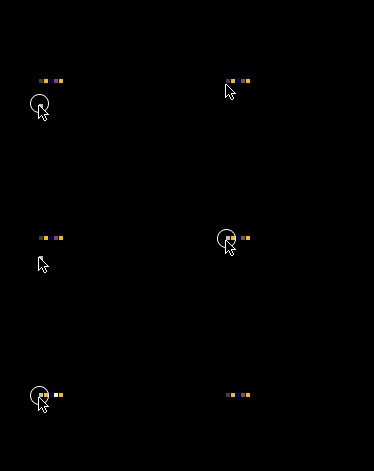
An OR gate is a logic gate that will output HIGH if either of its inputs or both of its inputs are HIGH and the easiest to make in TPT as it consists of 2 diodes with the output connected together.
AND Gates
An AND gate will only output HIGH when both of its inputs are HIGH. It is the easiest-to-understand logic gate using the old technology.
XOR Gates
A XOR gate (eXclusive OR) will only output HIGH if one of its inputs is HIGH (not both). It is one of the more complicated gates to create at a small size in TPT, but luckily someone has already done that for you.
NOT Gates
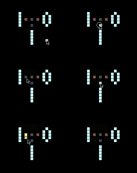
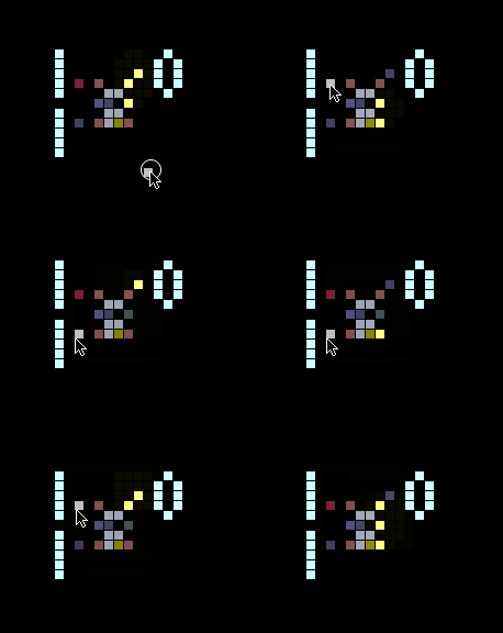
Unlike the other logic gates here, a NOT gate only has one input and will only output HIGH if the input is low. This is easy to do with PTCT, which will not conduct when heated.
NOR Gates
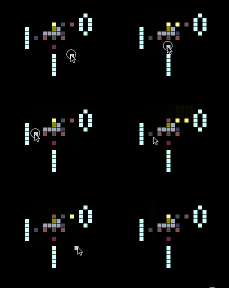
A NOR gate (Not OR) can be thought of as an OR gate with a NOT gate connected to the output. It will only output HIGH if none of its inputs are HIGH.
NAND Gates
A NAND gate (Not AND) can be thought of as an AND gate with a NOT gate connected to the output. It will only output HIGH if none or 1 of its inputs is HIGH.
XNOR Gates
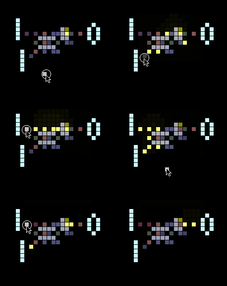
A XNOR gate (eXclusive Not OR) can be thought of as a XOR gate with a NOT gate connected to the output. It will only output HIGH if none or both of its inputs are HIGH.
Useful Electronic Devices
This section will show some useful basic electronic components that can be created with the elements shown so far.
SWCH Memory
Because SWCH maintains its state when turned on or off, it can be used to make the simplest form of memory in TPT:
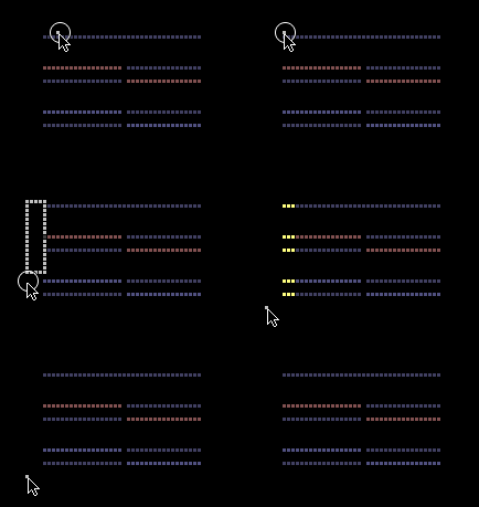
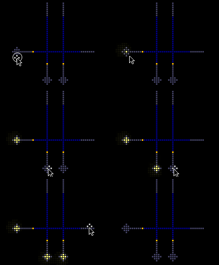
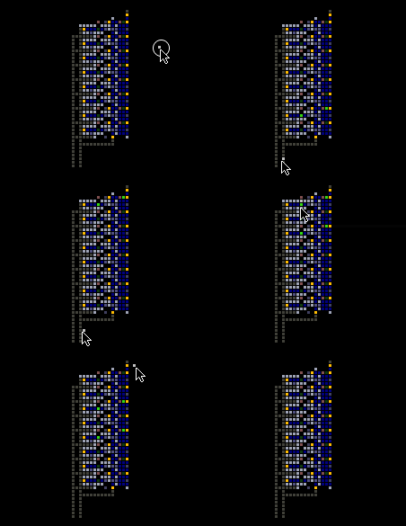
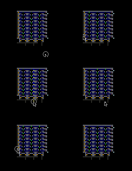
ARAY is used to spark PSCN within the conduction range of the SWCH, which turns it on, writing to the memory. INST is used to trigger ARAY which activates more ARAY directed through the SWCH. The BRAY will only pass through pixels of SWCH which are turned on by the PSCN, which effectively allows the memory to be read. Another INST-triggered ARAY sparks a pixel of NSCN next to each pixel of SWCH, which clears the memory.
SWCH memory can be made more compact, as shown in this example:
This is done simply by moving everything closer together, using INSL as needed to prevent unwanted SPRK transfer. SWCH memory can be made even smaller by layering, which is beyond the scope of this tutorial. Larger arrays of SWCH memory are also possible, but are now considered obsolete because of CRAY memory, which is shown later.
Shift Registers
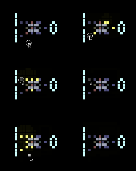
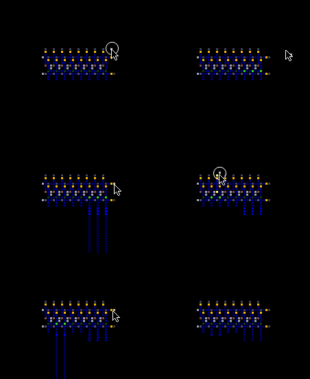
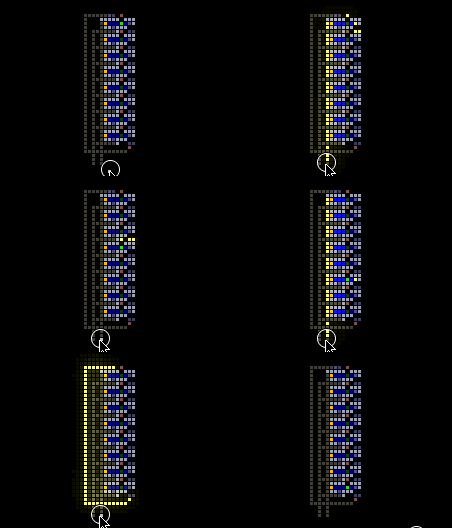
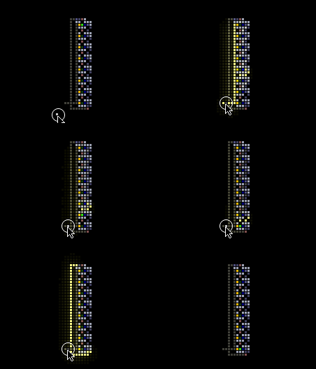
By modifying the concept of SWCH memory, a shift register can be made. A shift register takes input data, either as serial (a series of pulses on one wire) or parallel (pulses on several wires), and can shift it in one direction, giving either a parallel or serial output. A serial-in parallel-out shift register is shown below.
Parallel-in serial-out shift registers can also be created:
A simple serial data link can be made using a parallel-in serial-out shift register to send data and a serial-in parallel-out shift register to receive data. This is the same principle by which real-life serial data protocols like USB and RS-232 work in hardware. However, in TPT, there is a much faster and simpler way of sending data serially using BRAY and FILT wavelengths which is shown later.
Decimal Counters
A simple decimal counter can be made by connecting the last output of a serial-in parallel-out shift register to its input. The counter will increment by one every time the shift input is sparked:
By removing any unnecessary parts, it can be made even smaller:
Shift Register Latches
In order to read the output of a serial-in parallel-out shift register without shifting it, you can add SWCH memory to the output and connect the ARAY that reads the memory to the INST that shifts the register.
Decimal to Binary Converters
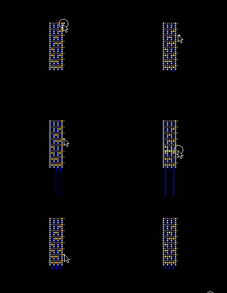
Another property of ARAY can be used to make a simple decimal to binary converter:
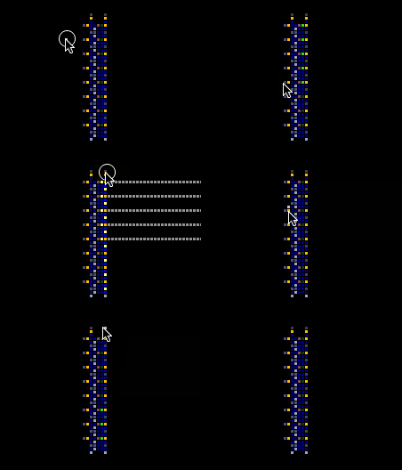
The horizontal ARAYs spark the NSCN, which sparks the INWR, which sparks the ARAYs that point to the output. This works because BRAY passes harmlessly through any INWR and ARAY in its path. The example only outputs a 3-bit binary number, but can easily be expanded.
Binary to Decimal Converters
Binary to decimal converters can be made by toggling SWCH in specific patterns for each bit and firing ARAY through it:
Binary to decimal converters using advanced ARAY techniques (shown later) are smaller but more complicated to make.
Using Other Electronic Elements
Using DLAY
DLAY is an electronic element found in the powered elements menu. It only conducts from PSCN to NSCN and creates a delay for an amount of frames determined by its temperature. The default temperature is 4 degrees, which will create a 4-frame delay.
Using FRAY
FRAY is an electronic element that pushes or pulls particles when sparked based on its temperature. A positive temperature will push particles and a negative temperature will pull on them. With a high enough temperature, a single particle can be accelerated enough to break GLAS.
Using STOR
STOR is an electronic element that stores a single particle and releases it when powered with PSCN. It can be used to precisely dispense single particles instead of using PPIP. It can also directly pass to an adjacent PIPE or PPIP without any PSCN input.
Using Sensors
There are 3 sensors in TPT which are all found in the sensors menu. They are DTEC, which sparks any nearby conductors if it detects a particle of its ctype in its detection range (this is set by tmp2, see the DTEC page for details), TSNS, which sparks any nearby conductors if it is touching a particle with a temperature higher than its own, and PSNS, which sparks any nearby conductors when the pressure is higher than its temperature.
Using Powered Elements
LCRY
LCRY is a powered element that is activated by PSCN and deactivated by NSCN. By default, it will change color to a lighter gray when turned on, but if it has a decoration color, it will be black when off and it will change to its decoration color when on.
PUMP and GPMP
PUMP and GPMP are powered elements that are activated with PSCN and deactivated with NSCN. PUMP will create pressure equal to its temperature and GPMP will create gravity equal to its temperature (Newtonian Gravity must be enabled.)
HSWC
HSWC is a powered element that is activated by PSCN and deactivated by NSCN. When turned off it does not conduct heat, but when turned on it conducts heat quickly.
PCLN/PBCN/PVOD/PPIP
These are all powered elements activated by PSCN and deactivated by NSCN that act as CLNE, BCLN, VOID, and PIPE when turned on.
Using CRAY, DRAY, and PSTN
Using CRAY
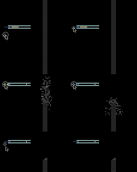
CRAY is similar to ARAY except that it emits a beam of any other particles. The particle type that it emits can be set using its ctype or by drawing over it with an element. The temperature of the emitted particles is determined by the temperature of the CRAY.
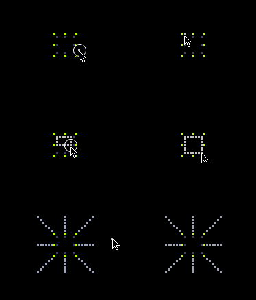
CRAY can emit particle beams in 8 directions:
The tmp property of CRAY changes the length of the particle beam...
and the tmp2 property changes the number of pixels skipped before the beam starts:
By placing FILT in front of CRAY, the decoration color of the emitted particles can be set:
CRAY Modes
CRAY can be used in different modes by sparking it through different elements:
When sparked through METL, the CRAY beam will stop at the first particle other than FILT in its path. When sparked through PSCN, the CRAY beam will, for every pixel in its path, if the pixel is occupied by a particle it will be erased, and if the pixel is not occupied by a particle one will be created. When sparked through INWR, as many particles as the CRAY's tmp value will be created, ignoring but not overwriting any particles already in its path.
Using DRAY
Using PSTN
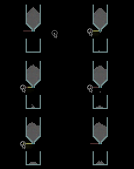
PSTN is an electronic element that moves other particles. The most basic way to use PSTN is to place two pixels of PSTN with a pixel of PSCN and NSCN each one pixel away. PSTN extends when the PSCN is sparked and retracts when the NSCN is sparked.
By default, PSTN is sticky, meaning it will pull particles back when it retracts. This can be changed, as you will see later.
A common way to use PSTN in electronics is to place a particle of METL or DLAY so the PSCN conducts to it and then to the NSCN so the PSTN automatically retracts.
Using FRME
When PSTN pushes one particle of FRME with others touching it, all of the FRME particles will move at the same time. This allows PSTN to move many particles at once.
FRME can be made non-sticky by changing its tmp value to 1.
Using PSTN's Temperature
The distance by which PSTN extends each frame can be controlled by either making the PSTN longer and moving the PSCN and NSCN further away from the extending end, or by setting the temperature of the PSTN. PSTN extends by its temperature in degrees above 0C divided by 10 and rounded to the nearest whole number, summed over all PSTN particles from the one receiving the spark to the one at the extending end of the PSTN, all minus one particle.
This save demonstrates how to use PSTN's temperature to make PSTN that can instantly extend the distance specified by a binary input:
Other PSTN Properties
PSTN's ctype determines what particle type it will stop extending at if it hits.
PSTN's tmp2 can be used in a similar way to limit the maximum extension length.
PSTN's tmp can be used to set the maximum number of particles it can move.
Advanced ARAY Usage
Erase BRAY
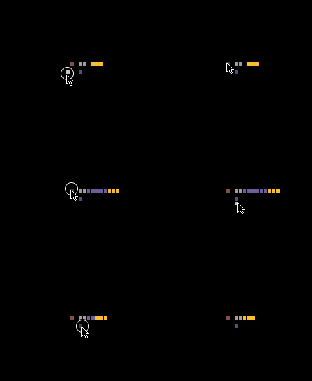
When ARAY is sparked with PSCN, it creates orange BRAY called erase BRAY. Erase BRAY does not spark objects, disappears in 2 frames, unlike normal BRAY which disappears in 30 frames, and erases any other BRAY in its path.
INST-ARAY and PSCN-ARAY can be combined to fire normal BRAY which is then quickly erased, allowing the normal BRAY to spark its target every 4 frames without needing FILT in its path..
ARAY life property can be changed to make BRAY disappear faster or last longer allowing for a custom ARAY cooldown.
Binary Counters
FILT ROM
Faster Logic Gates
CRAY RAM
ARAY and FILT Wavelengths
FILT and SPRK
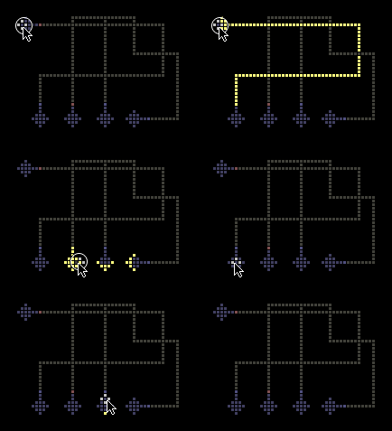
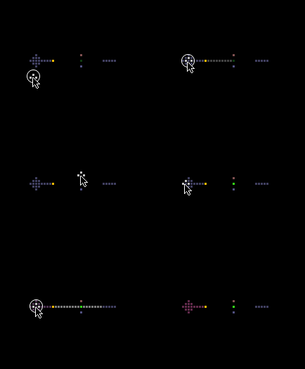
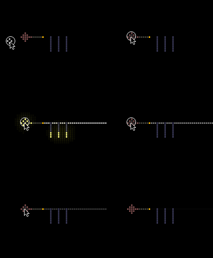
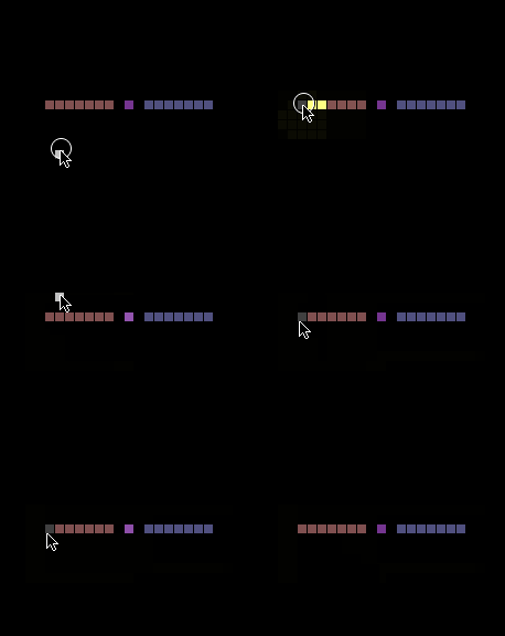
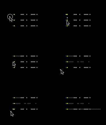
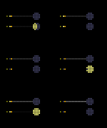
Working with parallel SPRK data is simpler but the machines are large and clunky; working with serial FILT data allows for more compact and faster machines, but FILT bits are more complex. What if you could have the best of both world's; now you can.
Here are designs for a parallel SPRK to serial FILT converter and a serial FILT to parallel SPRK converter:
